Agricultural Joystick Components: A Practical Sourcing Guide
A closer look at the shaft, mounting base and wiring harness behind a control lever, and the details to settle before ordering custom parts.
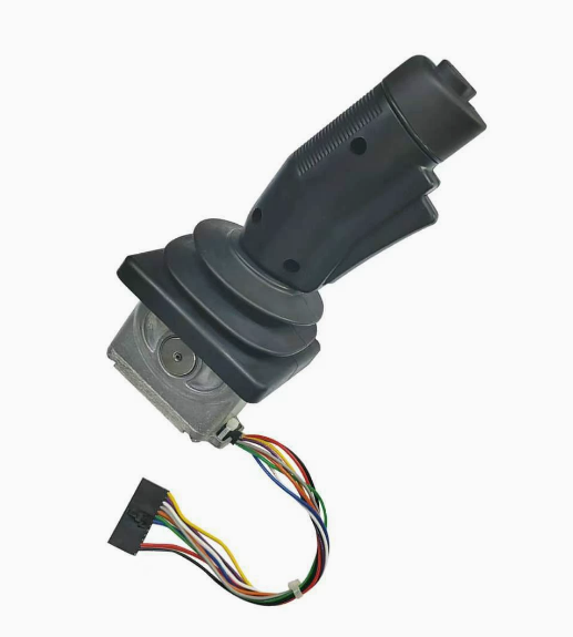
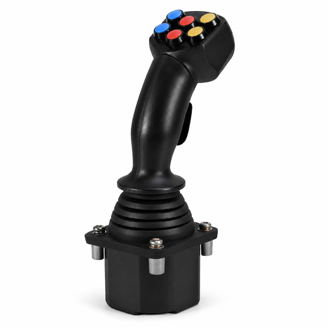
The grip is the part an operator sees. The shaft, mounting base and electrical connections are the parts a sourcing team needs to get right.
When sourcing agricultural joystick components, a matching appearance is only the starting point. A shaft must fit its mating features, a base must locate the assembly, and a harness must connect the intended circuits without interfering with movement. Those requirements belong in the drawing and specification, not in assumptions made from a photograph.
Source the component against its interface, not just its shape. The images in this guide illustrate assembly and component geometry. They do not establish material grades, dimensions, electrical ratings or interchangeability between the two joystick examples.
01 / Assembly contextStart with the complete control lever
The two assemblies above show why a joystick should be reviewed as a system. The grip, boot, metal mechanism, mounting features and wiring occupy the same limited space. A change to one part can affect the clearance or position of another.
Before quoting an individual component, identify what it touches, what moves relative to it, and how it is located during assembly. Include a section view or an assembly model when those relationships are not clear from a standalone drawing.
| Component | Interface to define | Information to supply |
|---|---|---|
| Shaft | Mating bore, cross-pin, thread or retaining feature | Diameters, datums, fit requirements and thread callouts |
| Mounting base | Mounting face, fasteners and central mechanism | Hole pattern, mounting datum and critical seat geometry |
| Wiring harness | Joystick terminals and machine-side connector | Connector part numbers, pinout, wire specification and routing length |
A component drawing should make these relationships measurable. An assembly drawing then confirms that the individual requirements work together.
02 / The metal shaftJoystick shaft: define the critical features
The shaft shown below has stepped cylindrical sections, a threaded end and a transverse hole. Each feature needs a purpose on the drawing: locating a mating part, accepting a fastener, or controlling the position of an adjoining component.
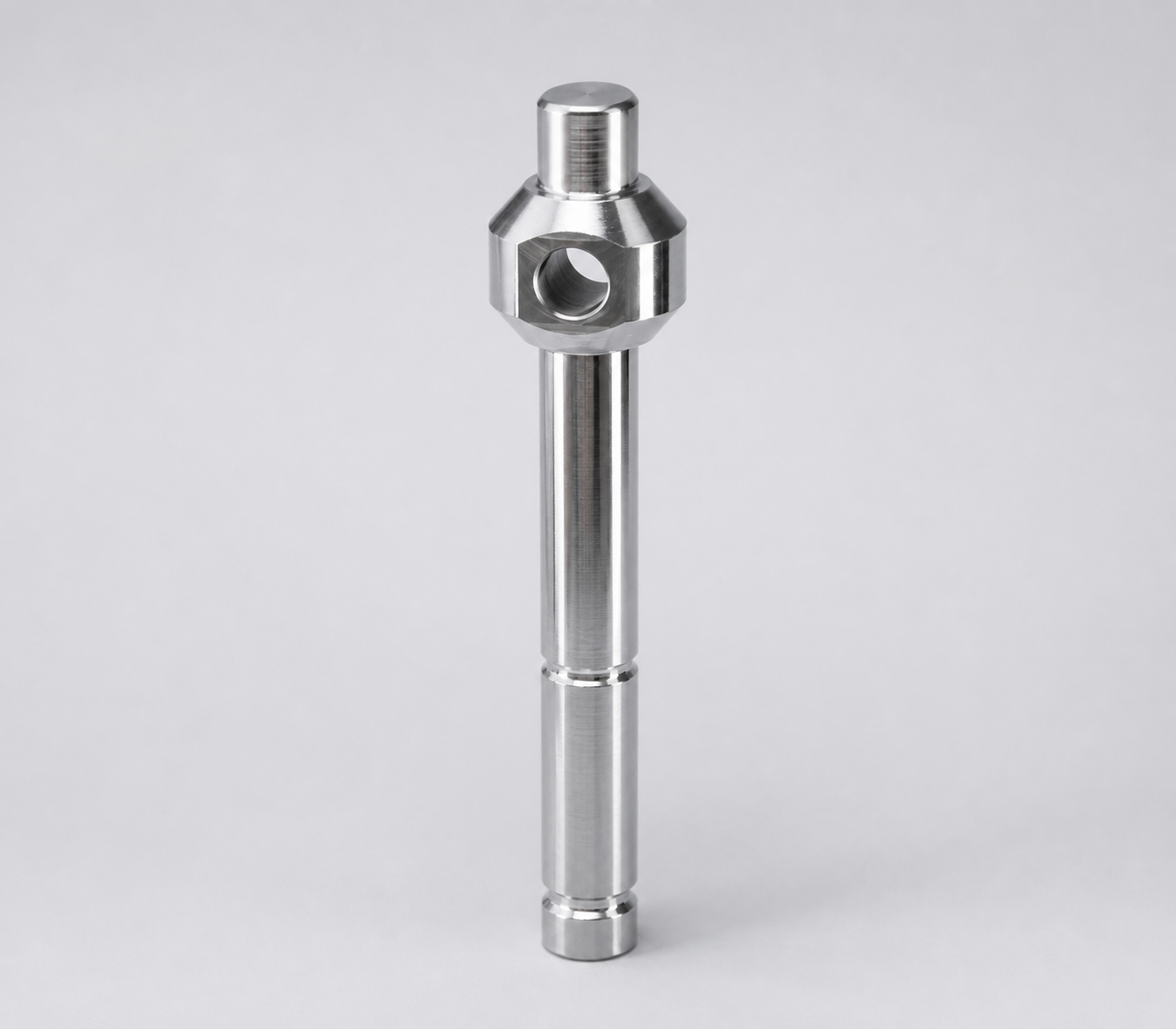
What belongs on the shaft drawing?
- Functional diameters: identify the sections that run inside a bore, bearing or bushing, and specify the required fit.
- Cross-hole position: define its diameter and location from a functional datum. State its angular relationship to any flats or other indexed features.
- Threads and shoulders: include the thread standard, size, pitch and usable length, together with the shoulder dimensions that control seating.
- Contact surfaces: identify any finish or edge requirements at moving interfaces instead of applying the same cosmetic treatment everywhere.
CNC turning is a route to evaluate for the rotational features; cross-holes and flats can require additional operations. The final route should follow the drawing, material and order quantity. Do not assume that a polished appearance identifies the alloy or its treatment.
03 / The mounting baseMounting base: define the assembly datums
The base example combines a broad plate, mounting holes, a raised central feature and lower lugs. Its manufacturing review starts with the mounting condition: which face seats against the machine, which holes locate it, and which features must align with the joystick mechanism?
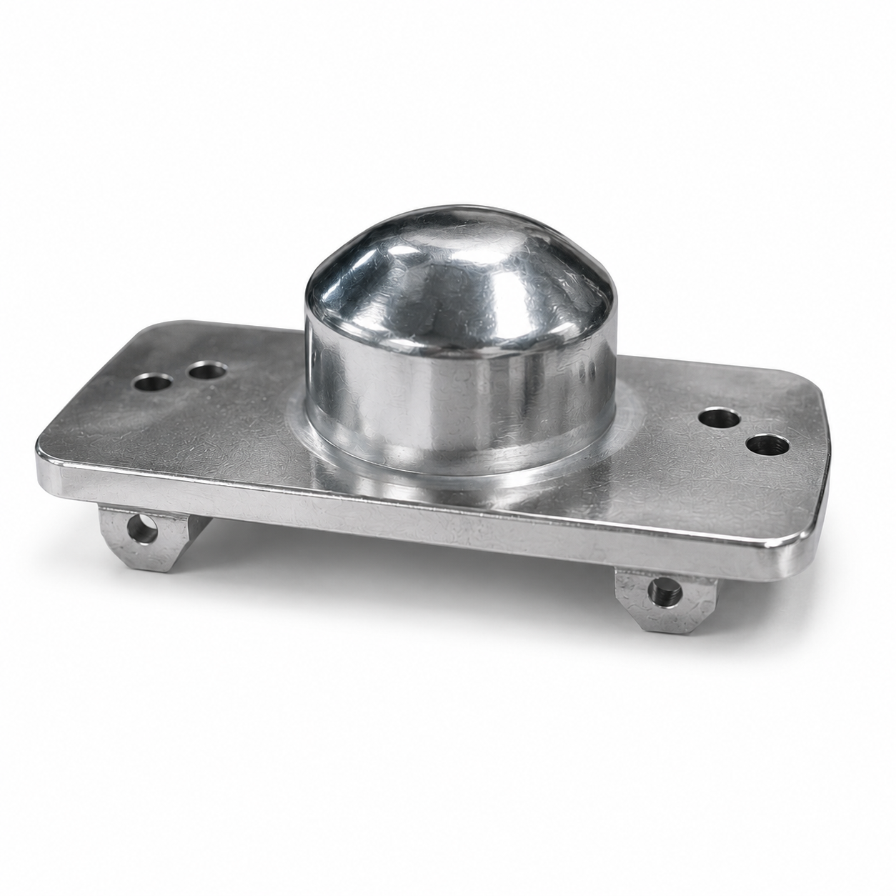
Mark the mounting datum and the features that must stay aligned to it. Where function requires it, specify flatness, hole position or perpendicularity, and agree how those features will be inspected. Leave clearance and nonfunctional surfaces under appropriate general tolerances.
The visible shape alone does not tell a supplier whether the part is machined from solid, formed, cast or assembled. Ask for a proposed manufacturing route and identify any surfaces that must be finish-machined after earlier operations. CNC milling may be relevant to the locating faces, hole pattern and other specified geometry.
Show the installed condition. A section view through the central mechanism and the mounting face can communicate more than a list of isolated dimensions.
04 / Electrical integrationWiring harness: specify the connections
The harness shown here connects a rectangular connector to a circular connector through a set of colored wires. Color and connector appearance are useful for identification, but neither is a complete electrical specification.
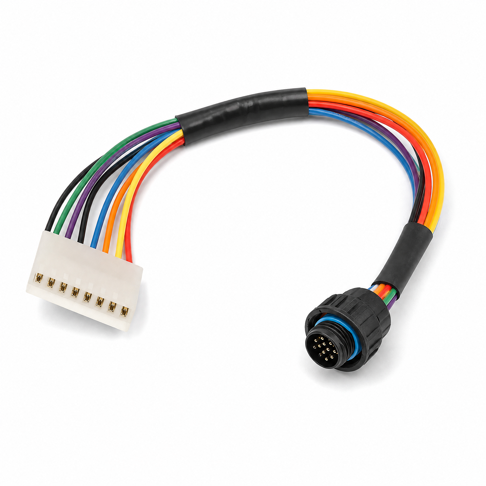
Provide a pin-to-pin wiring schedule with connector and terminal part numbers, wire gauge, insulation requirements and finished lengths. Define where the harness is secured, what moves near it, and where strain relief or abrasion protection is required.
Ask the electrical supplier to confirm the applicable checks, such as continuity and pin assignment, against an agreed specification. Environmental protection, electrical ratings and machine compatibility must be verified for the complete installed system; they cannot be inferred from a connector seal or a product image.
For a machined-component order, keep the harness requirements available as assembly context. If the project also includes electrical supply, define that scope separately with a qualified supplier.
05 / Manufacturing decisionsAgree fit, material and finish together
A material name, a finish description and a tolerance block should tell one consistent story. Start with the operating conditions and the mating parts, then specify what the component needs to do.
- Material: name the grade and any required condition or treatment. A photograph cannot distinguish similar-looking alloys.
- Finish: state the process and the surfaces it applies to. Identify any areas that need masking or a different finish.
- Final dimensions: make clear whether critical sizes apply before or after finishing, and review the complete tolerance stack at mating interfaces.
- Acceptance: agree the measurements, visual criteria and any documentation needed before the first batch is made.
Avoid copying a tolerance from an unrelated part or setting one tight limit across every feature. The useful question is what each interface requires, and whether the proposed process can consistently produce and verify it.
06 / Your quotation packageWhat to send before production
A clear request lets suppliers quote the same scope. For a joystick shaft or mounting base, prepare the following package:
- Matching model and drawing revisionsInclude the 3D model and a dimensioned PDF. Mark datums, threads and critical characteristics on the drawing.
- Material and finish requirementsState the material grade, treatment, finish and any masking or cosmetic requirements.
- Assembly contextShow mating parts, installation orientation and movement clearances. Include the harness routing where it affects the mechanical design.
- Quantity and delivery expectationsSeparate prototype quantity from expected repeat orders, and state the required delivery date.
- First-article acceptanceAgree which features will be measured, what records are needed and who approves the sample before a larger release.
HXD Precision can review the machined-part scope against your drawing. Send the shaft, base and assembly requirements together so the quotation can identify the proposed process and any details that still need clarification.
07 / Common questionsBefore you order joystick components
Can you quote a part from these photographs alone?
A photograph can begin the discussion, but it does not define a production-ready part. An accurate quote needs dimensions, material, quantity and the relevant tolerances. If only a sample is available, agree a drawing and verification process before production.
Are the two joystick assemblies interchangeable?
These images do not establish interchangeability. Confirm the mounting pattern, movement, electrical interface and application requirements against the original specifications before selecting a replacement.
Which dimensions on a shaft or base need tighter control?
Start with the features that locate, mate or move: shaft fits, locating shoulders, pivot features, mounting faces and relevant hole positions. Define their datums and allowable variation from the assembly requirements rather than assigning the same tight tolerance to every surface.
Does this guide specify a material or protection rating?
No. The photographs illustrate geometry, not a verified material grade or an environmental rating. Those requirements must be stated in the component specifications and, where applicable, validated on the installed assembly.
Can the shaft and mounting base be quoted together?
Yes. Send both drawings, matching model revisions, quantities and assembly context through the quotation page. Identify any electrical or complete-assembly requirements separately so the supply scope is clear.
Let’s review your joystick components.
Send your shaft or mounting-base drawing, material, quantity and finish requirements. Start with a clear manufacturing scope.
Send Drawings for a Quote