Mechanical Joystick Base Assemblies
From a single unit to a prepared shipment. A workshop view of mounting interfaces, batch handling and protective packing.
Discuss Your Component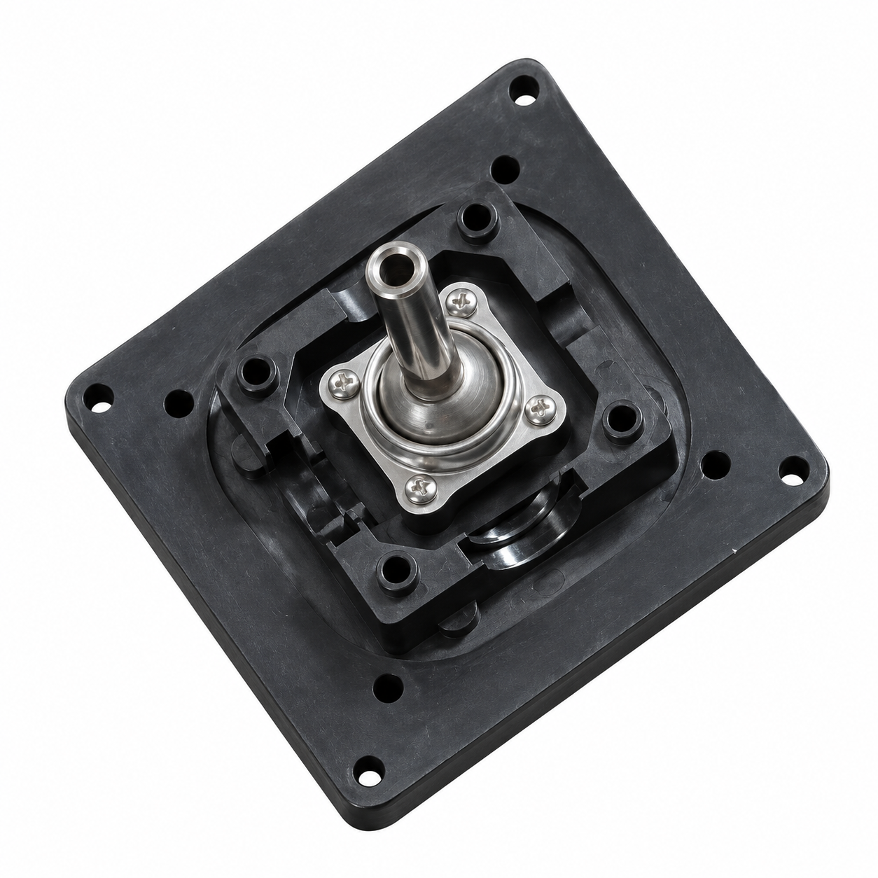
A mechanical joystick base brings together the mounting plate, shaft and moving mechanism. For a buyer, a useful enquiry starts with how those interfaces fit the application and how the assembly will be supplied.
The photographs and short videos in this article show the components in the workshop, followed by individual protection and carton preparation. They give the drawing review a practical point of reference.
Define the interfaces before the batch
The pictured units combine a square black mounting plate, a projecting metal shaft and a silver retaining flange with fasteners. The approved drawing should connect these visible features to the requirements of the mating assembly.
Mounting plate
Confirm the outline, thickness, hole pattern, mounting orientation and clearance within the customer’s housing.
Shaft connection
Specify the exposed length, diameter, end features and fit with the handle or other mating component.
Assembly condition
Agree the included parts, fasteners, required motion and acceptance checks. State material and finish requirements for each supplied component.
For a custom shaft enquiry, see our CNC turning services. Our joystick component sourcing guide covers the wider mechanical and electrical interface discussion.
A closer look at the actual batch
The photograph shows the assemblies collected in an open carton. In the accompanying clip, one unit is lifted and handled to show the shaft and base arrangement more clearly.
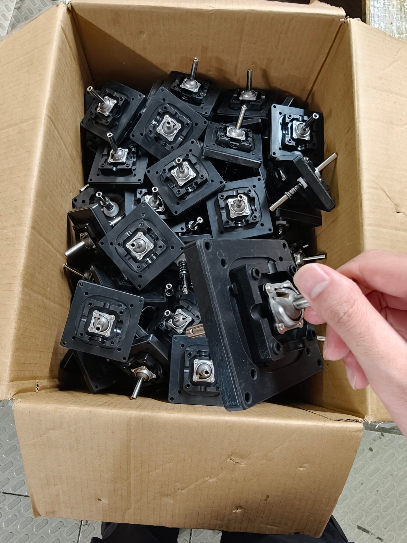
For production approval, connect this visual review to the agreed drawing revision and inspection scope. Specify any movement, load or durability checks required for the application at quotation stage.
Individual protection inside the carton
The packing clip shows individually wrapped components placed in separate cardboard compartments. Wrapping separates the parts from surrounding surfaces; the dividers keep neighboring units apart.
For your order, identify protruding shafts, finished surfaces and contact points that need protection. Agree the quantity per carton, separation method and any special cleanliness or corrosion-protection requirements.
Prepare the outer shipment
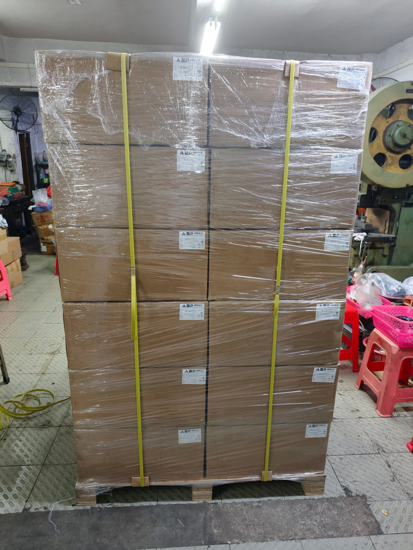
The outer arrangement should match the delivery route and receiving conditions. Confirm package dimensions, weight, labeling and handling requirements before dispatch. For the complete handover discussion, see our precision parts packaging guide.
What to send for a clear quotation
- Current drawings2D drawing and 3D model, with revision and part numbers.
- Component requirementsMaterials, finishes, critical dimensions and mating fits.
- Supply scopeMachined components, mounting parts, assembly work or a complete supplied unit.
- Quantity and acceptanceSample and production quantities, inspection records and required functional checks.
- Delivery requirementsPacking instructions, destination and target schedule.
If the application includes sensors, switches or wiring, include the electrical specification separately so the complete supply scope can be reviewed.
Common questions
Can we enquire about the shaft or mounting parts separately?
Yes. Identify the required parts and send their drawings, materials and quantities. We will review the manufacturing scope for those components.
Can we specify our own packing arrangement?
Send your packing instructions with the RFQ, including protection, quantity per carton and labeling requirements. The agreed arrangement should suit the parts and delivery route.
What is needed beyond a reference photograph?
Provide the dimensional and material specification, required assembly condition and inspection scope. Photographs support the initial discussion, while the approved requirements define the order.
Discuss your component or assembly
Send your drawings, quantity and supplied-condition requirements. Include packing and inspection needs for a project-specific review.
Send Drawings for Review